Facebook: "ten!
4:05amMe
lmfao
4:06amCaitlin
when you read all this tomorrow you are going to be like wtf?
4:09amMe
oh yeaaa
i'm still gunna print it though"
Saturday, August 7, 2010
Tuesday, June 22, 2010


Wednesday, June 16, 2010
Tower Crane Specs: Title Blocks (Ortho.)
The Orthographic Views of the Arm of the Crane:

Ortho Views for the Hold of the Arm (arm is inserted into hold):

Tower Truss Ortho views:

Ortho Views for the Hold of the Arm (arm is inserted into hold):

Tower Truss Ortho views:


Tuesday, June 15, 2010
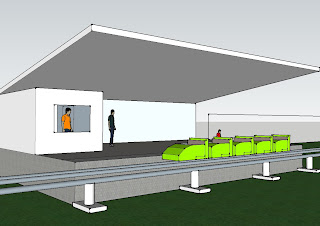
Roller Coaster Project Final
The following are a few screen shots of the designed and animated (Google SketchUp) Roller Coaster, as well as an actual animation of the cart view as you ride the roller coaster.


The Animation of the ride:


The Animation of the ride:
Monday, June 14, 2010
Journal: Week 18
Tuesday June 15/10:
Worked on the Orthographic views for the Truss structure, have to finish and then all thats left are the orthographic views of the entire structure.
Monday June 14/10:
Continued work on the Orthographic views of the Hold. Still have to add Leaders to the ArmOrtho and finish the Hold, as well as the TrussOrtho and over all views of the crane.
Wednesday, June 9, 2010
Journal: Week 17
Wednesday June 9/10:
Continueing work on the arm of the crane, having difficulties designing the views.
Continueing work on the arm of the crane, having difficulties designing the views.
Friday, June 4, 2010
Journal: Week 16
Friday June 4/10:
Today I continued to renovate my design of the cross and hold, with the tower of the crane already comleted.
Thursday June 3/20:
Created the Cross and Hold basic shape and measurements, have yet to design the actual truss structure, as well as the Shape and dimensions of the hold.
Wednesday June 2/10:
Having some difficulties designing the truss structure of the tower of the crane. However the basic shape and dimensions of the base/tower are built.
Tuesday June 1/10:
Made the tower of the crane, however it did not work out as expected, adjustments required.
Designing and rebuilding the tower to alter the specifications.
Monday May 31/10:
Finished the slideshow with 18 slides, all research completed regarding the crane structure. Beginning the initial design of the base of the tower crane. Note: leave room for adjustment, adjustments may be required.
Monday, May 31, 2010
Organizational Processes
Group Problem Solving Principles:
Define the problem
Stay objective
Skills:
Brainstorming
Facilitation and mediation
Process improvement
Clarify what will be done with the priorities before using any of the above methods
Brainstorming Guidelines:
Identify a recorder and facilitator
A Process Improvement Model:
Aim (the aim of the process)
Reality (How do things actually happen)
Root Causes
I
V
E
Friday, May 21, 2010


Thursday, May 20, 2010
The Engineering Design Process
Elements of Design: The Process
-Problem Identification
-Research Phase
-Requirements Specification
-Concept Generation
-Design Phase
What is the Problem?
-Collect info
-Interpret information
-Organize needs hierarchy
-Determine relative importance of needs
-Review outcomes and process
Concept Generation and Evaluation
Explore many solutions:
-Brainstorm
Select the best solution
-Based on needs and constraints
Creativity
-Development of new ideas
Innovation
-Bringing creative ideas to reality
Concept Generation
-Substitute
-Combine
-Adapt
-Modify
-Put to other use
-Eliminate
-Rearrange or reverse
Design Group (Team)
-Engineering projects require diverse skills
-This creates a need for group (team) work
-Select members based on skills
1. Technical
2. Problem-solving
3. Interpersonal
-Develop Decision making Guidelines
1. Decision by authority (leader)
2. Expert Member
3. Average member opinion
4. Majority
5. Consensus
Project Management
Define for each activity
1. Work to be done
2. Timeframe
3. Resouces Needed
4. Responsible Person(s)
5. Previous Dependent activities
6. Checkpoints/deliverables for monitoring progress
Notes:
MAX height 50cm
http://moodle.sjconline.ca/file.php/123/PrinciplesDesign.ppt#257,2,Elements of Design the Process
Wednesday, May 19, 2010


Tuesday, May 18, 2010


Sectional Drawing Test Review
Part Drawings:
-Detail drawings completely describing the part, mostly done orthographically, completely describing a single element. (Specifications)
Assembly Drawing:
-Displays functional relationships between the parts. (Production)
Section View:
-Used to clarify internal detail and to avoid dimensioning to hidden lines.
-They are established by referencing a cutting plane.
Cross-Hatch symbols
-Different materials require (are depicted by) different patterns.
Half Sections
-The result of cutting planes being opositioned on parts in such a manner that only half of the resulting view or projection is shown in section. (Symmetry)
Offset Sections
-Allow us to provide greater breadth of detail with fewer section views. All of the features are alligned with the cutting plane.
Line Types
-Object, Hidden, Center...
Radial Dimensions
-To indicate the size of fillets, rounds, and radii.
Journal: Week 15
Monday May 17/10:
Watched the flim "World Trade Centre: Anatomy of Collapse", discussing the importance of proper planning and organization, sopecifications, and the leading causes to its destruction.
Tuesday May 18/10:
Posted all projects ever worked on.
Watched the flim "World Trade Centre: Anatomy of Collapse", discussing the importance of proper planning and organization, sopecifications, and the leading causes to its destruction.
Tuesday May 18/10:
Posted all projects ever worked on.
Monday, May 10, 2010
Journal: Week 14
Monday May 10/10:
Worked on the orthographic/isometric assignment package, completed most of the work, more time required, will finish tomorrow.
Tuesday May 11/10:
Completed the orthographic/isometric package, resumed work on the problems.
Wednesday May 12/10:
Mr.D described the significance of a rhombus. Began the Orthographic Drawing problem [Control Bracket].
Thursday May 13/10:
Finished the front and top views of the Control Gasket problem. Will finish the front view and hidden lines and dimensions.
Thursday, May 6, 2010
Orthographic Drawing Problem

This Orthographic Drawing Problem involved the use of the offset, copy and displacement functions as well as the use of hidden and dimension lines to indicate the details of the drawing.
Monday, May 3, 2010
Journal: Week 13
Monday May 3/10:
Began working on the Locating Guide Drawing
Tuesday May 4/10:
Completed the drawing, have yet to insert dimension and hidden lines
Wednesday May 5/10:
Worked on Orthographic and isometric projections.
Began working on the Locating Guide Drawing
Tuesday May 4/10:
Completed the drawing, have yet to insert dimension and hidden lines
Wednesday May 5/10:
Worked on Orthographic and isometric projections.
Monday, April 26, 2010
Journal: Week 12
Monday April 26/10:
Wrote a note on Dimensions, halfway through the AutoCAD assignment.
Going to work on the AutoCAD Problems once finished.
Wrote a note on Dimensions, halfway through the AutoCAD assignment.
Going to work on the AutoCAD Problems once finished.
Dimensions Note
What are Dimensions: The purpose of dimensions is to show the size and location for the features shown.
Why Use Dimensions: To ensure that the part made is the part you asked for.
Extension lines extend from to dimensions
Leaders cannot be vetical or horizontal lines, may be mistanken as the object.
Conversions:
Metric:
1" = 2.54cm
1" = 25.4mm
Imperial:
1' = 12"
196 cm = 6' 5"
1km = 1000m = 10000 dm = 100000cm = 1.0 x 10^5cm
Two Methods: Alligned and unidirectional.
-Do not place dimensions on the object
-Do not dimension to hidden lines
-Leaders should not be drawn at horizontal or vertical angles
- Complete circles are dimensions with diameters
Orthographic / Multi-View Drawing
Chapter 14: Quizes
Quiz 1

Quiz 2

Quiz 3

Quiz 4

Quiz 1

Quiz 2

Quiz 3

Quiz 4

Chapter 5: Quizes
Quiz 1


Quiz 2

Quiz 3


Quiz 4

Quiz 5

Quiz 6

Chapter 4: Quizes
Quiz 1

Quiz 2

Quiz 3

Quiz 4

Quiz 1

Quiz 2

Quiz 3

Quiz 4

Subscribe to:
Comments (Atom)